If you’re building or renovating, your architectural drawings will include more than just floor plans. Detailed diagrams like elevations, framing plans, wall sections and shadow diagrams are essential for showing how your home will be constructed—and how it will work with its surroundings. These drawings are also critical for council approvals and compliance with the National Construction Code.
Here’s what each of these drawings includes and why they matter during your renovation or build.
Elevations
Elevations are scaled drawings that show the external appearance of your home from each side—front, rear and both sides. They reveal wall heights, roof pitch, external finishes, window and door placements, and more.
Your local council will assess elevation drawings as part of your planning permit application. These drawings help them evaluate how your project fits into the streetscape, meets height limits and avoids overlooking neighbours.
Elevations are particularly important if you’re planning a second storey or building on a slope, as they show how your house will sit relative to natural ground level.
Framing plans
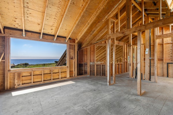
Framing plans show the layout of your home’s structural frame—including walls, floors and roof trusses. These are essential for your builder and must comply with AS 1684 (for timber framing) or AS/NZS 4600 (for cold-formed steel structures), depending on the materials used.
They include details like:
- Stud and joist spacing
- Beam and lintel locations
- Bracing and tie-downs
- Load paths and support points
If you’re reconfiguring walls during a renovation, these plans help determine which walls are load-bearing and what needs reinforcing.
Wall sections
Wall sections are vertical slices through a part of your home, usually drawn at a larger scale. They show how different components come together—from the foundation up to the roof.
Wall section drawings often include:
- Footings and slab or stumps
- Wall framing and insulation
- Vapour barriers, cladding and linings
- Floor-to-ceiling heights and roof structure
They’re crucial for demonstrating how your home meets thermal performance and moisture management requirements under the NCC. Good wall sections also make it easier to identify how insulation and vapour barriers will be installed.
Shadow diagrams
Shadow diagrams show how your building casts shadows at different times of the day and year, usually at 9am, 12pm and 3pm on the winter solstice (21 June). These are often required for planning approval, especially if you’re in a built-up area.
They demonstrate:
- How your extension or second storey affects neighbouring properties
- Whether nearby homes or private open space will lose winter sun
- Compliance with local overshadowing regulations
If you’re adding a pergola, verandah or second floor, a shadow diagram will show how your design affects light access for you and your neighbours.
Why these drawings matter
Each of these documents forms part of your overall building permit or planning submission. They’re reviewed by your builder, certifier and council to ensure your home complies with relevant codes and won’t negatively impact others.
When renovating, these drawings can help prevent costly mistakes—like cutting into structural framing or breaching height limits. If you’re working with a draftsperson or architect, make sure these documents are included in your plans and tailored to your specific site conditions.
For more technical drawing insights, see:


