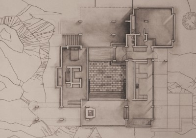
House plans are drawn up by the architect or building designer to tell the builder exactly what needs to be built. Learn how to understand the finer details on house plans.

Design’s arguably the most important part of building (or extending) a house. As well as being an incredibly complex thing in its own right, it’s especially crucial that the building designer or architect is able to express through their drawings exactly what needs to be built, in a way that ensures the builder knows what’s required.
Consider some of the kinds of things that need to be communicated properly:
- specific material choices
- exact product models and sizes (e.g. for windows, kitchen appliances)
- where different plumbing systems need to go
- how electrical systems will be incorporated
- how the roof will be constructed
- the layout of frames and structural elements
- exact dimensions and orientation for every single part of the house
- etc.
When you’re building or even extending a house, the smallest misunderstanding of what’s intended can have awfully expensive consequences. If a window’s not the right size, for example, it probably won’t fit into the (already constructed) wall – meaning that either your extremely expensive sealed, double glazed windows will need to be changed, or that the wall will need to be altered to accommodate them. That’s just one of many examples, of course…
What sorts of diagrams are used?
The sorts of diagrams that the architect or building designer will make will depend on the type of house that’s being built. Below are a few of the sorts of plans that you’ll likely see, and an explanation of what they represent:
- Site plans – these map out the building site, including the slopes and gradients, as well as things like trees and rocks and the immediate area around the site. Site plans are generally supplied in twos, including a ‘before’ plan that shows the site as it is, and an ‘after’ plan that shows the precise location of the proposed construction.
- Floor plans – these are a detailed top-down view of the layout of the house. Floor plans give a good idea of where everything will go, and include information about the sorts of materials and products that will be used.
- Elevations – Elevations are diagrams of the house showing how it will look from one particular side. Interior elevations may also be used to give a better idea of how a particular part of the interior should look.
- Wall sections – These diagrams are a cross-cut section of a given part of the house, designed to give a very detailed look at how the house is put together. In these diagrams you can expect to see how framing, wall surfaces, sheathing, foundations, roofs and many other things are arranged.
- Framing plans – To ensure that the house is structurally sound, it’s important that the framing is appropriately designed and built. Framing plans detail the way that house frames need to be built.
- Shadow diagrams – These diagrams are used to show what kinds of shadows the proposed building will cast, both on your own property and on your neighbours’ yards. Shadow diagrams usually depict the shadow at its ‘extremes’ (e.g. winter solstice).
Common features on house plans and diagrams
To make them more easily understood, diagrams and plans are (in theory) required to stick to certain conventions in terms of the way things are laid out and drawn.
House plans, including floor plans, framing plans, site plans, elevations and so forth should be drawn so that they adhere to the Australian Standard AS1100 (Part 3: Architectural Drawing). This Standard sets out what information should be provided, where on the page things should be listed, and – quite specifically – how different things should be drawn, abbreviated and annotated.
While different architects and building designers might use a little creative license in their designs and represent various things slightly differently depending on the software they use, it’s vital that what’s being shown is clearly represented in a way that leaves no room for misinterpretation.
Below are a few of the common elements you can expect to see on most house plans and diagrams:
- Title block – the title block explains:
- what the drawing is (i.e. site plan, floor plan)
- what revision of the drawing you’re looking at
- who drafted it
- your details
- the architect or building designer’s details
- the address or location of the site
- the date
- Scale – unless they’re preliminary sketches, formal plans and diagrams should be drawn precisely to scale. The plan you’re looking at will usually represent the scale both as a ratio (e.g. 1:200) and as a block or granulated scale.
- Orientation – plans and diagrams must show which direction north is in relation to the diagram you’re looking at. Where possible, the drawings for a given project should use the same orientation for the sake of consistency and clarity.
- Callouts – These small symbols indicate where further detail is provided in a separate diagram.


